|
|
|
|
 |
|
|
Proven Plants
Gasification plants have a long history. They began with the production of charcoal 40,000 years ago and were taken into more advanced development 200 years ago for the production of coke and town gas. Without charcoal and coke, the production of metals would not have been possible. After the first oil crisis many wood gasifiers were built in the USA, which were decommissioned when the oil price fell. In Europe, the building of wood gasifiers began around 15 years ago, which are partially still in use. One of the most famous plants is in Güssing (southern Austria). Gasification plants are also starting to be installed to serve remote communities in Asia and Africa.
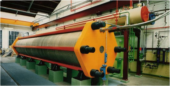
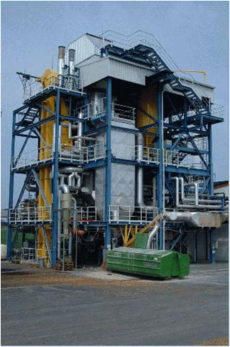
The wood gasifier in Güssing is shown here. Its capacity is 8 MW. The plant has been in active operation since 2001. It is a pressureless fluidised-bed gasifier with a diameter of 1.6 metres. If the system had been under pressure of 30 bar, a plant of the same size would have had a capacity of around 200 MW. The reactor is heated by a circulating sand bed, which is heated in a second reactor by a partial burning of the biomass. The synthesis gas produced drives two gas motors each of which produce 2 MW of electricity. The waste heat is used to supply the town of Güssing.
The plant is used intermittently as a research system for different syntheses under the direction of the Technical University of Vienna. In a larger scale the production of synthetic natural gas and the production of Fischer-Tropf liquid fuels becomes possible. So far the production of pure hydrogen from biomass has only been investigated in computer simulations and scientific reports. The cold gas efficiency result for this simulation is given as 60%. The cold gas efficiency is the proportion of the calorific energy of cold hydrogen to the calorific energy of the biomass actually used, Since synthesis gas is produced without pressure, a large amount of electrical energy is required for separating the hydrogen by pressure swing adsorption (8-20 bar).
A similar type of plant of 20 MW is located in Ulm in Germany. In this case the synthesis gas is also used to produce electricity. The heat produced is connected into the the district heating network.
There are further plants in Scandinavia. The city of Göteborg has a plan to provide the entire city with synthetic natural gas from thermochemical wood gasifiers by 2020.
|
|
|
|
Problems of producing hydrogen from biomass
Processes should be developed with the end product in mind. Hydrogen for fuel cells should be produced at high pressure. The pressure is enables the supply of hydrogen to the pipe network (natural gas network) without pumping stations, and is also necessary for cleaning the hydrogen using a pressure swing adsorption unit.
A further challenge is the removal of tars. In current systems the tar content is the greatest nuisance. The types of gasifiers now used on an industrial scale produce synthesis gas with a tar content of between 2,000 and 20,000 ppm. Elaborate tar washing with bio-diesel can reduce tar content to 50 ppm. For gas engines, this is low enough - but not for fuel cells, which require a tar content of less than 1 ppm.
If such gasifiers are to be used nationwide, the materials must be used in a sustainable closed cycle. The ash must be suitable for use as a fertilizer in fields, because the use of artificial fertilizers is a huge problem in view of the forecast shortage of inexpensive phosphorous.
New technological approach to the production of hydrogen from biomass
For the above reasons, the following requirements should be met:
- The gasifier should be operated under pressure
- A fluidised bed reactor is advantageous, because any fusing of the ash can be more easily avoided.
- The tar content should be reduced to <10 ppm by primary steps (in the reactor itself).
The first requirement suggests an improvement of the entry system for biomass. The use of lock systems has so far proved to be complicated and expensive. A self-sealing screw has been patented, but has yet to be proven.
A problem when operating fluidised bed reactors lies in introducing the necessary heat for gasification without overheating the ash particles. For systems with a separate reactor and burner (Güssing) this is difficult, because individual particles can reach temperatures of 1100°C. This is above the ash fusion point for feedstock from annual plants. Then only wood is really suitable.
The use of nickel containing particles for reducing tars as fluid bed material (as is done in Güssing) is also undesirable, because the discharge of nickel containing ash on fields is prohibited.
|
|
|
|
|
|
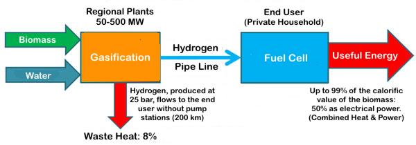
Energy chain of an innovative process
An ideal gasification plant would deliver the whole gross calorific (HHV) energy of the biomass as hydrogen. [That is 107% of the net (LHV) calorific energy of the biomass.] With waste heat of 8% at a large gasification plant, a fuel cell at the end user can still deliver heat and power amounting to 91% of the gross biomass energy. Higher investment into very large gasifiers could perform even better. The high efficiency of a hydrogen economy is very evident.
Since the potential supply of biomass is larger than the demand for energy, very high efficiency is not very important. Poorer efficiency simply increases the proportion of heat which can usually be put to use where it arises. In a hydrogen economy, a shortage of heat is assumed.
|
|
|
|
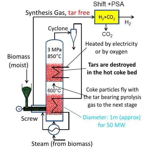
Simplified flow diagram of the innovative process
In the upper section of the reactor the tars are catalytically destroyed by coke particles. A low tar content is necessary for the catalytic shift reaction and the pressure swing adsorption unit. The supply of the energy to sustain the reaction is only implied here. Innovative apparatus which does not lead to the overheating of ash particles will be required here. The partial burning of biomass in oxygen would be a good method, because in the medium term, oxygen will be available free from nearby electrolyzers.
The diagram shows how this heat from the upper section is applied to the lower pyrolysis section of the gasifier where the biomass is first broken down into large molecules and coke particles which pass to the higher temperature upper section where the steam reforming process breaks these down into small hydrogen and carbon monoxide molecules. The gas, which is still hot, then preheats the steam and biomass before passing to the shift reaction where the carbon monoxide reacts with more steam converting it into carbon dioxide and more hydrogen. Such heat management is the mark of an expert chemical engineer.
The dimensions and power output shown indicate that such a gasifier cannot be built arbitrarily small. The Güssing plant pictured earlier, were it operated under pressure, would have a power output of around 200 MW for a plant of the same dimensions. Industrial plants operated under pressure would therefore be much more compact, and also low cost. In order for the innovative features of this design to function the plant should not be operated at much less than 50 MW. A 50 MW plant requires approximately 10 tonne/hour of biomass (with respect to its dry weight). The hydrogen produced could supply a small town of 30,000 inhabitants its total electricity, heat and mobility requirements. According to a rough estimate the costs of such a plant amount to around 30 Million Euro . For a pilot plant, one would therefore have to plan for around 60 Million Euro. H2-Patent GmbH can advise on commercial utilization.
Several inventions of H2-Patent GmbH are employed in the processes shown. One area is the the system for feeding biomass into the pressurised reactor vessel. Another is the integration of at least two fluidised bed reactors in series to make the synthesis gas tar free. A third is a heating system using oxygen, in order to avoid the fusion of the ash.
The suitability of these innovations has now been confirmed by the Fraunhofer Institute UMSICHT. Using computer simulations, an exceptionally high net cold gas efficiency of over 83% has already been predicted using only a simple method of waste heat recovery. This value is not absolute, because it could be improved by further investment. As with all process engineering plants, a compromise between efficiency and investment must be found.
|
|
|
|
|
|
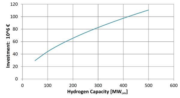
Investment costs for a hydrogen plant including an air separation unit
It can be seen in this graph that the costs do not rise linearly with the size. Experts agree that a 50 MW plant is the smallest which is technically controllable. Plants larger than 500 MW would require rail access or a port.
An air separator to supply oxygen, which accounts for around 30% of the investment costs, is included in the calculation. For small plants, the delivery of oxygen by road tanker is more economic. In the longer term, oxygen can be used from electrolyzers which produce hydrogen from renewable electric power.
|
|
|
|
|
|
|
|
Wood pellets cost around 4.8 ct/kWh
Hydrogen from wind currently costs around 7 €/kg
|
|
|
|
The experts who make the proposals for renewable energy for the German federal government, make their calculations according to VDI 2067, as is done here.
Large companies calculate larger profits. Experts from this field can determine the costs under different investment costs assumptions.
|
|
|
|
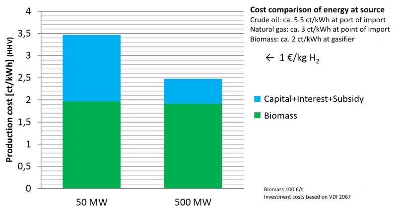
Production costs of bio-hydrogen
The production costs for hydrogen from biomass are shown for mature production plants at a biomass price of 100 €/t (dry weight equivalent at the plant), which corresponds to around 2 ct/kWh. The price of wood could fall back to levels seen before the 2008 financial crisis. In 2005, the price of wood was around 50 €/t.
The cost of using left over waste still needs to be clarified. Normally the supplier has to pay waste disposal costs. The way cost is affected can be read from the graph. Forest and farm residues make up around half of the potential biomass. The hydrogen prices shown are relative to the gross (HHV) calorific value, and can therefore be compared to a household natural gas bill.
The graph contains two messages:
- The price of hydrogen will be largely defined by the price of biomass.
- A hydrogen plant can provide hydrogen at 2.5-3.5 ct/kWh (at the edge of the town) which is less than than from distributors of natural gas (around 4 ct/kWh)
The first point shows that capital cost does not dominate. It is even less significant for large plants. It is therefore not particularly important that this cost be accurate.
The second point is worrying in that in the long term the price of natural gas is predicted to increase faster than for biomass. The cross border price trend in Europe over the past 15 years clearly showed this. The lower energy prices in a hydrogen economy and the ability to produce all fertilizers from biomass also has a downward effect on prices. This situation is not threatened by fracking for natural gas as the extraction costs in Europe are around 6 ct/kWh.
As already mentioned in the introduction of the concept description, the distribution of gas to households costs around 1 ct/kWh and to industry < 0.3 ct/kWh. Assuming a hydrogen price of 3 ct/kWh from the plant, domestic energy (half heat / half power) can be produced for 4 ct/kWh. Even if tax were still to be paid, it would still be significantly less than todays electricity price of around 30 ct/kWh. Even if hydrogen were initially produced from natural gas, and offered to domestic customers at 6 ct/kWh, it would still be more worthwhile than the current situation.
|
|
|
COMMENTS:
When biomass is burned or co-fired in power stations it has to be dried out first. The means either the expenditure of energy to dry it, or storage in a dry place for an extended period. The biomass gasifier proposed here can use biomass with its natural moisture because the water is necessary to the reaction. There is a cost incurred in drying biomass to fire in a power station which is avoided in the gasifier. On the other hand dry biomass costs less than moist to transport. Biomass transport costs may therefore be higher to supply a gasifier.
Unlike K-H I am not a chemical engineer, and have found the names applied to various types of thermal gasification rather confusing. Understanding them clarifies the ingenuity and importance of the design proposed by K-H. Here is some of the technical jargon:-
* WATER GAS (not to be confused with German Wasserstoff!) is the production of syngas (Hydrogen + Carbon Monoxide) from coke. This gas was originally produced by heating coal (or sometimes wood) to drive off flammable gasses which were used in early street lighting. This left behind coke (or charcoal) which was used to make iron and steel. As the use of the gas increased there was a surplus of coke. It was then discovered that if the coke was fed air to burn until it reached a high temperature, the air supply could be switched over to water (or steam) and then the chimney became filled with a flammable gas that could be added to the coal gas. This gas is called synthesis gas or syngas. The reaction with water is known as STEAM REFORMING. Town Gas was a mixture of both coal gas and syngas, and was stored in huge gasometers. It was roughly 50% hydrogen by volume. We still use much of this Town Gas pipe work laid by these 19th century engineers to bring us natural gas which is over 90% methane.
* PYROLYSIS is the driving off of flammable gas and liquid by heating biomass in the absence of air. It leaves behind charcoal which has several uses: as a fuel for cooking, for refining metals, and as a soil conditioner. The volatile content consists of flammable gasses, liquids and tar. This tar condenses and tends to block the workings of equipment that uses the pyrolysis gas. The lower section of the K-H gasifier operates as a pyrolysis gasifier.
* TORREFACTION is similar to pyrolysis, but takes place at a lower temperature. Its main purpose is to drive out water content, but some volatiles are released. There is also some change to the structure of the material which seals it from moisture and prevents it from rotting. It is the preferred form for use in power stations as it is much less heavy to transport and can be stored in the open. There is some loss of energy in this process.
* PRODUCER GAS is syngas diluted with nitrogen. Many simple gasifiers have a single reactor stage operating at a temperature high enough to produce syngas from both the volatiles and the carbon content of the feedstock by reacting with water, but instead of feeding oxygen to sustain this reaction the gasifier is fed air. Air however is 80% nitrogen which dilutes the fuel value of the gas. It is nevertheless suitable for use in a motor-generator for the production of electricity.
* A SLAGGING GASIFIER is one which deliberately operates at such a high temperature that the ash melts into a solid slag. When mixed municipal waste, which may contain poisonous materials, is used as a feedstock much of the dangerous material is captured in the solidified ash. This cannot be used as fertiliser but can be used as hardcore in the foundation of roads.
* A PLASMA GASIFIER is heated by an electric arc which raises the feedstock to extremely high temperatures. This also a form of slagging gasifier.
Most of these gasifiers are small and operate on site where there is a supply of biomass and where their heat and gas can also be used on-site. There are many variations. Some are designed to maximise the production of charcoal, some as slagging gasifiers, some to produce gas to drive a motor-generator, etc.
The Lurgi gasifier however was a large coal gasifier. When sanctions were applied to S Africa during the apartheid era 97 such gasifiers were installed by SASOL to produce syngas in the first stage of the production of liquid fuels from coal. They are still in operation supplying syngas as a raw material for many chemical processes. Coal is plentiful in S Africa, but is has no natural gas. K-H would have been familiar with these large Lurgi coal gasifiers.
* Note that syngas from coal or biomass can be converted into methane (Synthetic Natural Gas) and many advocate this. However, this is an exothermic process and may result in excess heat at the production plant. Larger hydrocarbons such as in liquid fuels are very exothermic. K-H explained that all this excess heat would lead to inefficiency. Im not sufficiently expert to know if all this waste heat could be put to good use.
Note 1
If hydrogen is to be seriously considered as a means of storing electricity then oxygen as well as the hydrogen should be stored. The use of oxygen instead of air in a fuel cell raises its efficiency. I would expect the electrical round trip efficiency from renewable electricity to hydrogen and back to electricity to be 35 to 40% with air but 60-65% with oxygen which could make it almost competitive with other methods such as pumped storage. However, I know of no serious proposal to store electricity in this way. It is much better to treat the hydrogen as a fuel gas as K-H has done.
|
|
|
|
|